
One day, all the CRTs and all the original consoles will be gone, and I’ll be eternally grateful for the efforts of those who preserved it all.
This story began for me with a tweet. David Shadoff posted that the RGB palette on the popular multi-system emulator Mednafen for the PC Engine module (released as the TurboGrafx-16 in North America) was not the same as a real PC Engine’s composite out. I would later find out that this phenomenon had been documented for some time, but I’ll get to that.
Today I learned that the PC Engine's RGB output is less accurate than its composite video output. At least, RGB should not be used linearly.
This means current emulators, RGB modifications, and FPGA solutions are all wrong.
(images show composite versus Mednafen). pic.twitter.com/kQlMZbxhHA
— David Shadoff (@Shadoff_d) June 20, 2020
David also posted the information to the PC Engine Software Bible Forums:
https://pcengine.proboards.com/thread/979/improper-colors
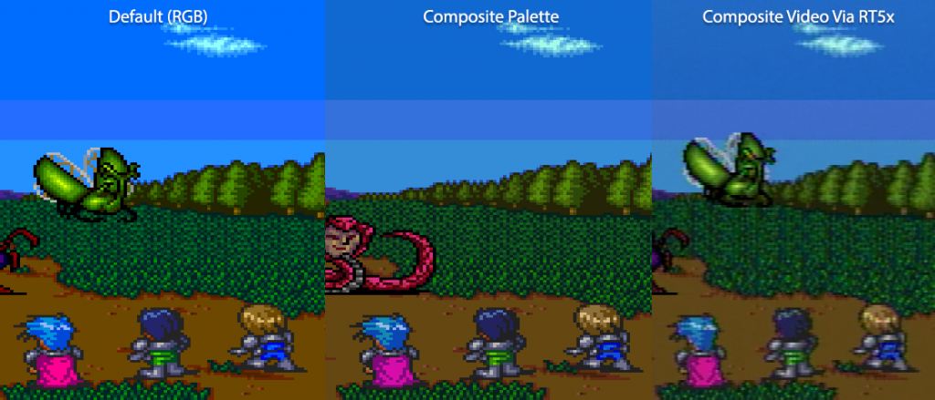
In this particular example, the game “Startling Odyssey II” demonstrates the issue nicely in its outdoor battle scenes. The blue sky gradient should show a three colour transition from light to dark blue. However when using Mednafen’s linear RGB to YUV palette lookup, it almost appears as if one of the colours is missing. Why is this? Allow me to digress from our story for a moment.
The science behind both human colour perception, as well as techniques to encode colour to make it more amenable to broadcast standards for televisions, is deep and complex, and requires lengthy study well beyond what this tiny article can cover. But one issue that is commonly found within colour science is linear versus non-linear colour encoding. What this means is that, with “linear colour”, the scale of brightness of a given colour or shade is linear – each step along the scale is equal in terms of light energy. Human colour and brightness perception does not work this way – we perceive colours on a non-linear scale. Similarly CRT television brightness is non-linear, and to compensate, technologies such as gamma correction exist to solve the problem. The Wikipedia page on gamma correction illustrates this nicely with a simple rendition of both scales:
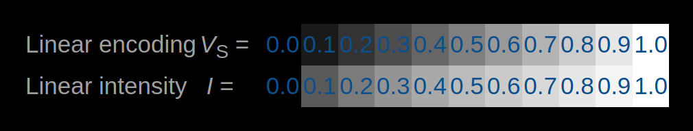
On top is the gamma corrected scale. On the bottom is the true linear scale.
Notice how the top scale which is non-linear appears “more correct” – the shades of grey appear “even” and there’s no larger or smaller jumps in how light the consecutive shades appear. On the bottom linear scale, the jump from 0.0 to 0.1 seems large, and the jump from 0.9 to 1.0 seems small. This phenomenon is sometimes part of what we call “crushed colour” (there are other reasons for this too, outside the scope of this article), or loss of detail because the scales of lightness appears incorrect.
But to really blow your mind, which shade in both examples seems to be “half brightness”, or middle grey? On the bottom (linear) scale, 0.5 looks like “half brightness”. On the top (non-linear) scale, closer to 0.7/0.8 appears like “50% brightness”. Non-linear scales at work, as our human brains crave more detail in subtler shades.
So it turns out that a slightly similar problem exists with the PC Engine. Internally, it’s own colour tables are non-linear. Raw RGB information when mapped directly to the YUV colour space (a colour system very similar to [but not exactly the same as] YIQ, both of which are used in various NTSC and PAL colour standards for broadcast television for reasons I won’t go into here) is not correct. Tapping pure RGB from the PC Engine when doing an RGB mod results in colours that are slightly different to what is seen when we look at either composite or S-Video output on the device, as it passes through an encoder that apparently has some sort of LUT (Look Up Table) internally. Like our gamma correction example above, the colours need some sort of “correcting”, and without it we notice several colours that should have larger differences between them “crushed”, appearing too close together.
But should we bother? What’s “right” and what’s “wrong”? This question becomes more and more important when we talk about preservation of video games, particularly when the display aspect of this art form is so critical to the experience. There’s often discussion in all art forms over the “artistic intent”. Whether it’s “film maker mode” on modern TVs that ensure the picture is similar to what you’d experience in a cinema, or the conversation retro gamers have over stretching 4:3 content to 16:9, or whether or not scanlines add to the appeal of a scaled up image. In a similar discussion, we wonder what the original artists intended when working on PC Engine titles, and whether or not they developed in pure RGB numbers, or simply from a colour palette tested on a real PC Engine with its default output. It seems likely that, using the “Startling Odyssey II” example above, that the latter was true. And even then, ignoring artistic intent, at the very least from a preservation standpoint, efforts should be made to demonstrate what a real PC Engine on a real CRT (acknowledging that the diversity of hardware in “real CRTs” was enormous too) should be documented.
And so this brings us back to our plucky team of hardware hackers, who took it upon themselves to find out what this specific colour correction was for the PC Engine.
The story starts much earlier, with work from turboxray dating all the way back to 2019:
https://pcengine.proboards.com/thread/857/games-composite-rgb-colors
Using Chris Covell‘s PC Engine palette generator, it was noticed that in greyscale, the “lightness” (Y value, or Luma) only seemed off between RGB and composite modes on a modded PC Engine. This discussion continued for some time, and within the 240p Test Suite PC Engine Discord channel and similar discussion, Tiangfeng posted the following images in mid 2020. On the left, an RGB modded PC Engine. On the right, composite out. To the same CRT:
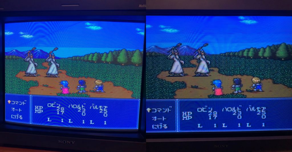
While the RGB clarity is evident over composite, the sky definitely shows the “crushed colours” error. Discussions around NES colours famous for being a console that doesn’t use RGB internally that requires pallet lookup tables, and how blending two other colours to make a third were possible scenarios. But ultimately it was demonstrated that this was very much a lookup error.
Discussions continued for some time. Hardware hacker Leo Oliveira and Chris Kennedy from Displaced Gamers joined in with expert opinion, joined by Damian Yerrick, aka PinoBatch, author of the NES 240p Test Suite port. RetroTink author Mike Chi brought in his expert colour knowledge on several occasions, as did long time MiSTer contributor and NES colour palette expert Jaime, aka Kitrinx/Rysha and NES pallet creator and video expert Firebrand X.
At this point, it was time to start measuring what was. 240p Test Suite author Artemio used an analogue vectorscope to measure various outputs. The device looks like this:
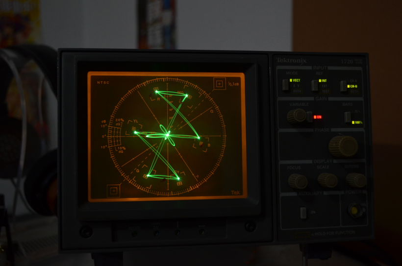
We see on this display a variety of markers that represent primary (Red, Green, Blue) and secondary (Cyan, Magenta, Yellow) colours in additive RGB colour space. Using patterns like the standard EBU (European Broadcasting Union) colour bars included in the 240p Test Suite, and tapped from a real console via the vectorscope, these can be measured for both their luminance/IRE values as well as the frequencies, mapped on to a radial chart:

With these highly objective tests, the team could now carefully compare consoles in different modes (RGB or composite), using the patterns provided by the 240p Test Suite.
Various methods were initially attempted – high res video captures, oscilloscope measures, and other methods. Bernard Bygott (no longer on Twitter, so I can’t link to his account) put a tremendous amount of time and effort into capturing and measuring individual colours (not forgetting that the PC Engine’s complete palette is 9-bit, resulting in 512 distinct colours – making testing all of them substantially more time consuming than the NES’ 54 usable colours). And while these produced satisfying results, there was agreement amongst the expert group that all of these methods left some level of subjectivity or variability in their results, compared to what was actually happening at a silicon level.
Finally, an incredible breakthrough. Efforts by hardware hacker Furrtek to decap the PC Engine’s HuC6270 video chip just a few months earlier resulted in some very highly detailed photos by John McMaster, covered here:
https://www.retrorgb.com/furrtek-maps-the-pc-engine-huc6270-with-john-mcmaster.html
Decapping physically removes the ceramic or plastic tops of chips and exposes their physical logic gates within. The process is both complex and dangerous (requiring special acids and solvents), and similarly photographing the literally microscopic internals to produce a useful picture is extremely difficult. When it works it produces a logic-level image of how the chip works, and people with the knowledge of how these logic components actually work can then investigate their internals, and reverse engineer details to incredibly accurate, if not perfect detail (and I ask forgiveness from the hardware experts reading – my knowledge of CMOS characteristics is not advanced enough to cover the difference between theoretical electronics and real world electronics).
What resulted was Furrtek discovered an important test function in the PC Engine hardware (exposed from the decap process), and was able to read the exact RGB to YUV lookup table, straight off the silicon!
Yay PC-Engine RGB to YUV lookup table dumped thanks to a test function discovered by observing the HuC6260 silicon.
Writing a small page about the process and to share the data.
Thanks for the help @Shadoff_d ! pic.twitter.com/77H02CXJZX— Furrtek (@furrtek) June 25, 2020
With this critical data at hand, and a huge leap in progress made, months of work and testing began. Rysha and Artemio worked tirelessly to convert these values mathematically into palettes, and put these into testing. Repeated testing was done on vectorscopes, oscilloscopes and with real games to see how these resulted on real world displays – again, hardware values from a chip, and real world characteristics can differ slightly thanks to the analogue nature of electronics, so a 1:1 mapping from chip math to data doesn’t always yield a perfect result. Saturation and luma levels required constant tweaking, and several months of effort were put in to getting the values precise.
And finally, after a few tweaks, a final palette was published, and committed to MiSTer.
https://github.com/MiSTer-devel/TurboGrafx16_MiSTer/commit/6e7a7c6d9cb034c78deaf1e231e84a492c5b3c60
Rysha went one step further and created a palette generator for people to make their own, published for public consumption:
https://github.com/Kitrinx/TG16_Palette
With this, any hardware mod, software emulator or FPGA implementation that supports the standard palette files (similar to those use on NES emulators / mods) can use either the palettes the team came up with, or their own if they prefer.
Bob recently tried this palette out on the Super HD System 3 PRO. He posted a testing video on the process, including guest appearance by Artemio who mentioned the work and team behind the palette creation:
https://www.retrorgb.com/super-hd-system3-pro-livestream-demo-and-testing.html
Sadly I don’t think I can truly capture the sheer scale of human effort that went into this change, nor the incredible teamwork that a group of strangers, spread across the globe, and brought together by their want for authenticity and accuracy within retro video game hardware were able to achieve. And all of them give away many months of hard work, backed by many years of training and expertise, for free. Something everyone can benefit from without spending a cent.
One day, all the CRTs and all the original consoles will be gone, and I’ll be eternally grateful for the efforts of those who preserved it all.
[A footnote to this article: I’d like to thank turboxray for bringing to my attention this documentation from 2010 that noticed these differences. Much further back than I’d ever realised! https://pcedev.wordpress.com/2010/12/30/composite-to-rgb-comparison-chart/ ]