Sega Genesis / Mega Drive 2 RGB Bypass
PLEASE READ: IT’S NOW RECOMMENDED THAT YOU INSTALL A SEGA TRIPLE BYPASS ON ALL MODEL 2 GENESIS CONSOLES!!! THIS GUIDE WILL BE UPDATED SOON AND VIDEO INSTALLATION POINTS CAN BE USED AS A REFERENCE, BUT MODEL 2 INSTALLATION PICS CAN BE FOUND HERE: https://www.retrorgb.com/genesistriplebypass.html
Genesis / Mega Drive 2 consoles do not require a modification for RGB-output, simply a cable. This page is an “experts-only” page that shows how to bypass the Genesis’ internal RGB amp with a different one. All details are below, but this mod requires you to make irreversible modifications to your Genesis system. Beginner and intermediate modders should not try this mod!

Please make sure to read the main Genesis RGB Bypass page before proceeding to make sure that this mod is something you’d really like to try!!! You must read the sections about sync requirements and RGB cables, as it might change the way you approach this mod!!! Also, there are many different revision Genesis / Mega Drive 2’s and each will look different inside. The model shown in this guide is a North American VA1 system and while the basic ideas are the same in all consoles, each mounting location and RGB points will be different. Use these instructions as a basic guide, but you’ll need to double check each detail on your console.
Tools / Parts Needed:
You’ll need a few tools for this mod (more info on the tools can be found in the tools section):
– Genesis Triple Bypass Board
– Excellent soldering skills.
– Philips head screwdriver
– Soldering iron / solder / flux
– Thin gauge wire
– Small, sharp, cutting tool
– Small pick or “dental tool” if you’re lifting pins
– Multimeter
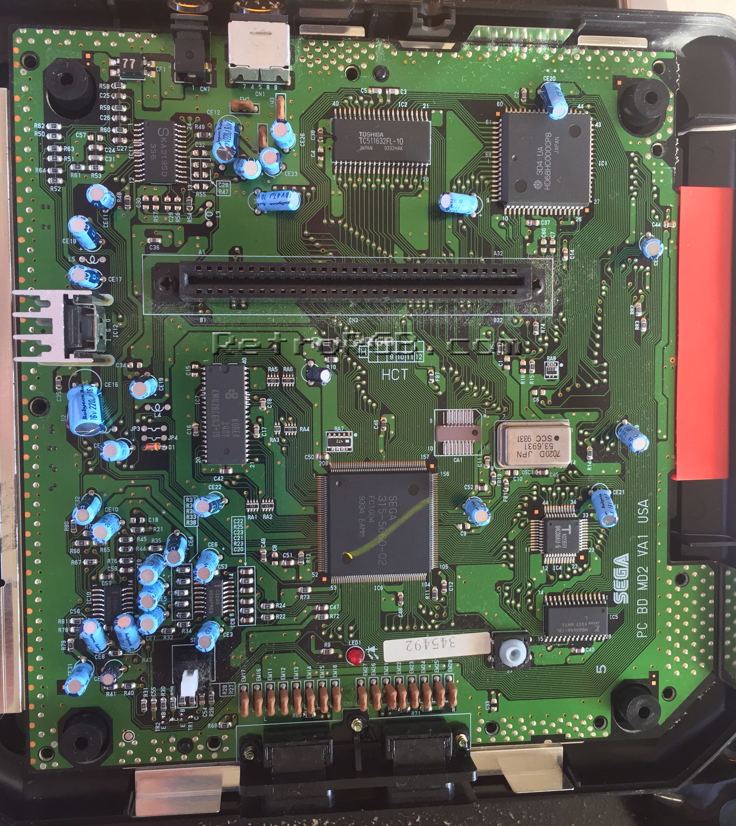
Completely disassemble the console and as you’re taking it apart, pay attention to potential mounting locations for the bypass board, that are clear and free of all components. I found the Toshiba chip near the multi-out to be perfect for this.
Next, find the main video chip. This model Genesis 2 has a VA1 motherboard installed and uses a Sega 315-5660-02 video chip. Click the picture below for full-sized:
You’ll have to research the pinout of your Sega chip. The 315-5660-02 outputs RGB on pins 35, 36 and 37 (respectively). You can solder directly to the pins, however it’s much easier to use your multimeter to trace the pins to an easier location. This board connects csync directly to the video encoder (we’ll talk about that later), but I found RGB points that were easily accessible on the board (click for full-sized):

Now you’ll have to prepare the multi-out port to accept the new RGBs signals. Unfortunately, there are no components on the board between the Sony CXA video encoder and the multi-out, so the only way to disconnect the old signals is by cutting or lifting. You can cut the traces on the bottom of the multi-out, but in my opinion this is very dangerous and only a last-resort option. If you’re careful, you can lift RGB-out pins 21, 22 and 23 and still re-connect them if you ever need to. Note that in some Genesis revisions (such as this one), the Sony CXA chip is labeled something different. As long as it looks the same, just use a multimeter to confirm pins 21, 22 and 23 connect directly to the multi-out before cutting, to verify that it’s the correct chip (click for full-sized):

Next you’ll have to deal with csync. In my VA1 motherboard, the sync pin #42 from the Sega 315-5660-02 is connected directly to both the “sync-in” pin 10 on the Sony video encoder and the multi-out; “sync-out” pin 11 isn’t connected to anything. You can try lifting the pin from the CXA, but if you do, you’ll disable composite video. Also, in this case, I actually think it’s safer overall to cut the trace on the bottom of the multi-out. I very carefully used a razor blade to make two small cuts right under the multi-out to the csync line (I wanted two cuts to ensure a clean break). Afterwards, I used a multi-meter to make sure both cuts properly severed the line. This is also a good time to add a wire to the csync pin, which will run to the bypass board (click for full-sized):

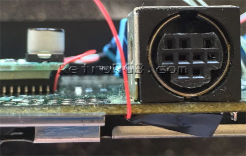
Then make sure to run the csync wire around the motherboard in a place where it won’t get pinched by any other components. I used a bit of tape, just to hold it in place:
After that, trim wires to length and connect the inputs and outputs of the bypass board. You’ll also want to get csync from pin 10 of the CXA chip, assuming you didn’t cut any pins. I found it much easier to solder RGB-out from the bypass board to via’s I found on the motherboard. If your revision doesn’t have those via’s, you’ll need to solder directly to the multi-out pins on the bottom of the motherboard.
Click for a full-sized picture of the entire installation:

Now, just re-assemble the entire console and make sure none of the wires are pinched by any of the shielding or plastic cover.
Summary / Tips:
– If the screen is too dark, your RGB cable most likely has 75ohm resistors in the console-side of the cable. If that’s the case, simply remove the resistors on the bypass board and bridge the connections (as shown in the above pic).
– If you’re still getting any kind of jailbars or screen noise after performing this mod, there’s some kind of interference. You can try using shielded cable for the mod, but on some model Genesis systems, there’s just too much interference on the board itself. In this case, I’ve lifted the RGBs pins from the Sega 315-5660-02 and connected them directly to the bypass board. This is an irreversible modification that should only be done if all other options have failed! Also, doing this will disable composite video, or S-Video (if you’ve done that mod too). I’d only do this as a last-resort option.
If you’re done, please head back to the main Genesis page. If you’d like info on mods for other systems, head to the Getting RGB From Each System page or check out the main page for more retro-awesomeness.