SNES Mini S-Video Mod
This page shows how to add S-Video output to a SNES Mini / Jr. system. I strongly suggest that if you’re going to mod your SNES Mini / Super Famicom Jr anyway, you’d might as well enable both RGB and S-Video at the same time. There’s cheap and easy boards available as well, making the installation easier overall.
S-RGB Expansion Board: Enable RGB and S-Video outputs using the console’s built-in encoder.
SNES RGB Bypass Board: Add a new RGB signal with a high quality amp, then add S-Video using the console’s built-in encoder.
Tools / Parts Needed:
You’ll need a few tools for this mod (more info on the tools can be found in the tools section):
– Soldering skills!
– The 4.5mm tool that opens the SNES
– Philips head screwdriver
– Soldering iron / solder
– Thin gauge wire
– Heat shrink tubing
– Two 75 Ohm resistors, the lowest tolerance possible:
http://www.digikey.com/product-detail/en/MRS25000C7509FRP00/PPC75.0ZCT-ND/595092
– One 0.1uf Capacitor:
http://www.digikey.com/product-detail/en/C320C104J5R5TA7301/399-9867-1-ND/3726105
– One 220uf Capacitor:
http://www.digikey.com/product-detail/en/RR71A221MDN1/493-3712-ND/2207248
S-Video Mod:
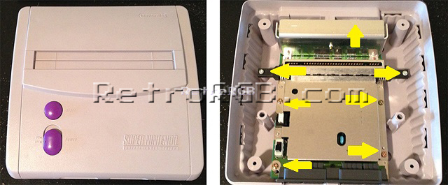
– Open the console by removing the 4 screws on the bottom of the case (using the 4mm SNES tool) and remove the 7 philips screws from the board. Then remove the heat shield, held in by three screws:
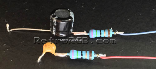
– Trim the negative end of the 220uf capacitor (usually the side marked with the stripe) and also trim an end of one the resistors to the same length. Add solder to each end, then solder them together. Do the same with the 0.1uf capacitor, but it doesn’t matter which end you use. If both components are properly tinned, it should be an extremely tight connection and they will not come apart. Then add wires and heat shrink tubing to the resistor side. The heat shrink tubing is important, as it will prevent the components from shorting out against any exposed metal.
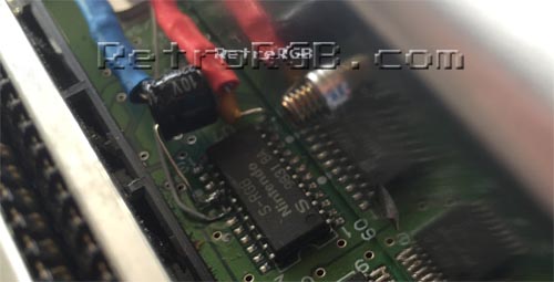
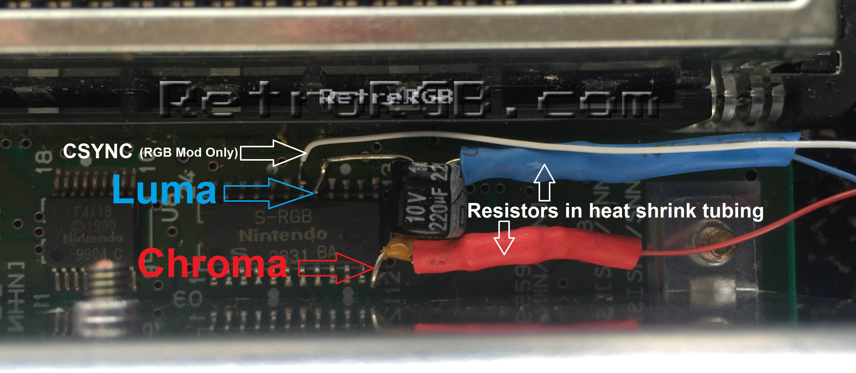
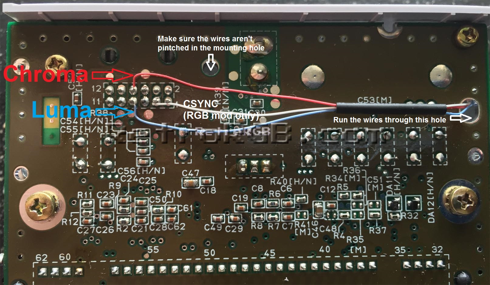
– Trim and bend the other ends of the capacitors as shown, then add solder to each end of the capacitor and each of the S-RGB pins shown in the picture below. The 220uf capacitor connects to luma and the 0.1uf capacitor connects to chroma. Make SURE the chroma capacitor is bent over the chip, or it will touch the heat shield when it is re-connected. Also, if you ever plan on performing an RGB Mod to your SNES, this is the perfect time to add the csync wire to the multi-out. It’s not required for the S-Video mod, but since you’re already soldering to the S-RGB chip, you might as well add it now. Click on the picture for the full-sized view.
– Replace the heat shield and carefully run the cables around it, making sure the cables aren’t pinched and nothing is touching the heat shield:
– Run the cables through the hole shown in the picture below (click for full-sized to show the entry hole), then trim the cables to their proper length. I added some heat shrink tubing to keep them together. Make sure that the wires are away from the mounting hole, then solder them to the pins on the multi-out shown below. Also, as stated above, the white wire is csync, which is not needed for this mod, but good to have in case you ever plan on adding an RGB mod.
That’s it! This will enable excellent quality S-Video output from your SNES Mini. It’s not as good as RGB, but may be a good choice for your setup.
Feel free to go back to the main SNES page. If you’d like info on mods for other systems, head to the Getting RGB From Each System page or check out the main page for more retro-awesomeness.