Most Genesis / Mega Drive model 1 owners have consoles with great audio, but terrible looking RGB. You can perform a bunch of different mods that remove the jailbars and interference, but at the expense of composite video. But now, thanks to Tianfeng, you can potentially have both. The project is still in beta and it’s up to YOU, the retro community to see how far we can take it. Everything I’ve learned about it so far can be found below and I strongly encourage expert installers to submit your installation and results for each MB revision to the wiki…
Genesis Subcarrier Bypass: https://www.retrorgb.com/assets/GenesisModel1SubcarrierBypass2022-10-18.zip
Genesis Wiki Page: https://consolemods.org/wiki/Genesis:Genesis_Mods_Wiki
First and foremost, this board is for people who’ve decided they want to use an original Model 1 Genesis via RGB or component video (YPbPr). While yes, you can get amazing FPGA recreations, there are many of us that – at least sometimes – prefer the original experience. And while Genesis composite video on a CRT is totally fine, the moment you step up to RGB, you can see how noisy the model 1 is. And that noise is doubled when you move from a consumer CRT to a PVM or BVM. Or worse, if you’re using a modern scaler and a big flat-panel TV, the jailbars are flat-out distracting!
Performing an RGB bypass, Sega Triple Bypass, or even just lifting the subcarrier pin will often fix this issue…but what if you sometimes want to play via composite and sometimes via RGB? Or, what if you just don’t want to remove functionality from the console? I could totally see a scenario where someone down the line ends up with the console, plugs it in, gets no video (or b&w video from composite) and assumes it’s broken.
If this is all resonating with you, there’s now a potential fix! You’re basically lifting the subcarrier pin (VDP pin 50 in most cases) and then re-routing it with shielded wire. This accomplishes on the motherboard, sorta the same thing that using shielded RGB SCART cables vs unshielded does externally – It moves the interference from composite video colors off the motherboard without affecting the other signals. I’ll show basic install pics, but the location of the board and wire routing might change between motherboard revisions. So, please consider this a beta and proceed at your own risk…
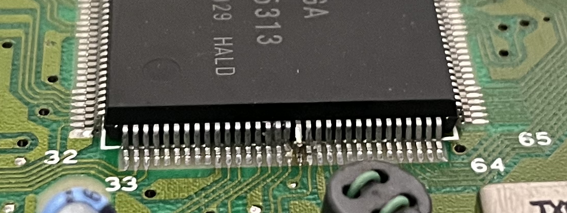
First, you’ll need to lift pin 50 on the VDP – The “subcarrier bypass” often talked about that disables composite video. Do this CAREFULLY by heating the pin with your soldering iron, then use a dental pick or razor blade to lift pin 50 from the pad. BE CAREFUL WITH THE PIN, as it’s both tiny and fragile!
When you’re done, check each adjacent pin to make sure they’re still connected and not bent or shorted:
Now stop here for a moment. You’ll want to power on your console and run some tests before moving on – First, is the console still working? If not, check every pin around pin 50 with a magnifying glass (or take a pic with your phone and zoom in). I’ve had the pin next to it look fine, but after a much closer inspection found it wasn’t fully touching the pad. A tiny bit of solder on the tip of my iron fixed that! Worse case, try putting the pin back down and see what happens.
Once it’s working with the pin lifted, load your favorite jailbar-testing game – I like Sonic 1. If the jailbars are significantly reduced like the “after” picture on the right, you can proceed:

If your Genesis still looks like the picture on the left – or worse – your motherboard revision might just be too noisy for this mod. If that’s the case, it’s best to either put the pin back down and leave it stock, or do a full RGB bypass. There’s one more thing you can try though, but I’ll put that at the bottom of this guide. Anyway, to continue…
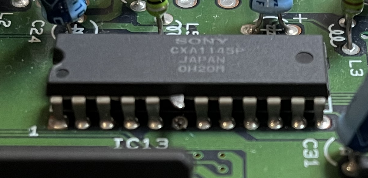
Next, lift pin 6 from the Sony CXA encoder. I used a desoldering iron first, then tried to carefully bend the pin up with thin pliers. I ended up breaking off the very end of the pin, but it still worked fine and I could still push it down and reconnect to the pad with solder if I needed to revert back to stock:
Now connect the bypass board between the CXA and VDP with shielded cable, making sure to connect ground on both sides. Proper wire management is absolutely crucial, otherwise you’ll break a pin off!
Here’s two examples of different install methods. First, I mounted the board on the VDP, pointing away from the oscillator, using some sturdy double-sided tape. I then snipped off a resistor leg and soldered it between the VDP pin and bypass board. There’s minimal pressure on the fragile VDP pin, as the tape keeps the board from shifting. I then connected the ground wire to a capacitor next to the VDP. And lastly, connected both signal and ground to the Sony CXA chip:


While the above installation worked fine on this motherboard revision, the results on your board might vary. You may need to determine a different ground point than the resistor leg, or even an alternate board location. Tianfeng suggested I try the opposite and put the bypass board on top of the CXA, instead of the VDP – Note that on this motherboard revision, the CXA chip is flipped!! ALWAYS double check!!!:

So far, I’ve done this bypass on an NTSC VA3, NTSC-J VA1 and PAL VA4. All resulted in an improved RGB signal, while retaining composite video, but the results were best on the PAL VA4. Unfortunately, that’s just how it goes with these old consoles – It’s possible no two are alike. If you have the skills to perform the mod and plan on using both RGB (or YPbPr) and composite, I do think it’s worth it though!
What happens if there’s still a lot of interference though? Keep in mind, analog video signals will never be perfect and if you’re using a modern scaler to display it on a giant flat-panel TV, expect some interference. But if it looks the same or worse then before the mods, there’s some troubleshooting you can do.
First, if you didn’t get jailbars with just the VDP pin lifted, but get them with the bypass board connected, check your cables, ground points and board location. And especially make sure you’re using a properly shielded cable as well. Definitely don’t give up, as we’ve already proven this can work (both via RGB bypass installs and this), but there’s always a chance you’ll find one specific motherboard revision that just doesn’t improve as much.
Next, if you got interference after just lifting the VDP, there’s one thing to try: Carefully scrape some of the solder mask at the end of pins 27 and 30, then solder a 4.7UF, 35v, 1206 SMD cap between them. Make sure you do NOT touch any other pins, just 27 and 30. Also, please note that this picture was taken from a 3BP install…DO NOT lift the RGB pins for this installation, or you’ll get no video at al!
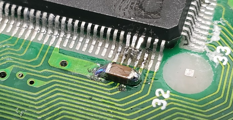
I tried adding the capacitor to see if it would further improve the video output after installing the subcarrier bypass and it did nothing. T’s results were the same. That said, if you have a motherboard rev that doesn’t improve after just lifting the subcarrier pin, maybe this will help??
And that’s all we have for now. If both composite and RGB work and you’re jailbar-free, consider posting pics on the wiki, along with any other notable things like if you did the RAM noise fix.