
This week I put out a video outlining how to take an accurate lag test of your controller. It’s a homebrew project you need to construct yourself with an Arduino Pro Micro and a little soldering. If you have ever used the MiSTer Input Latency database, this is the device that has been producing those results.
You start with the Arduino and wire one side into the controller and the other side into the MiSTer FPGA. The Arduino fires off a button press down one pin and waits for a return signal down another pin. It then calculates the round-trip time and this the basis for the lag tester.
- DIY Project
- Approx $15 in parts. Arudino costs ~10$
- Basic soldering required
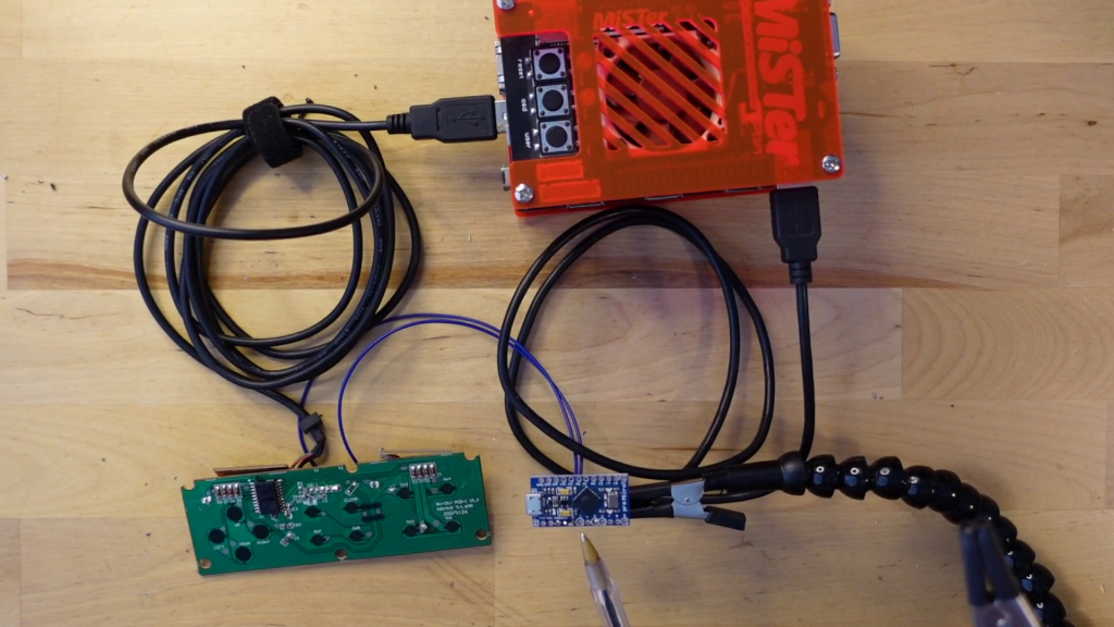
This unit uses a specially modified version of the NES core, so this contributes no lag. The special core is set to receive any button press and in turn generate a signal down the General IO port on the side of the IO board. That’s the port on the IO board which looks like USB3 but its not, its just data-lines using the convenient USB type plug. So we wire a cable from that USB-type port back to the Arduino.
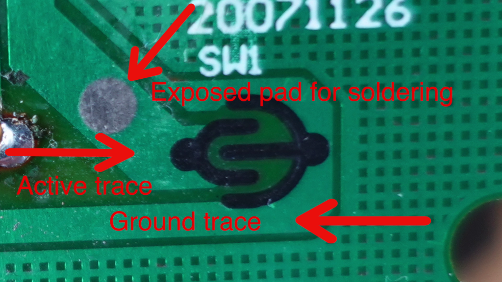
The tough part of this project is you need to solder onto the controller. There are two pins on the Arduino, you connect one to ground on the controller and the other to the active trace for the button you are pressing. I have found with modern controllers, the best option is around the shoulder buttons as they often have better exposed vias to solder onto.
The Arduino is now connected to the controller and to the general IO port of the MiSTer. The Arduino then fires off a signal down one pin and waits for an incoming signal on another pin. The code then calculates the round trip time and exports the results in a CSV format. Then you can take this file yourself and plug it into Excel or Google Sheets and work out your average time.


If you are interested in building this project, you can find full written instructions here or also check out the video below